Outlines are used to trace a roof surface or roof plane so that you can add keepouts, viewsheds and modules to a design in Scanifly.
Creating Outlines
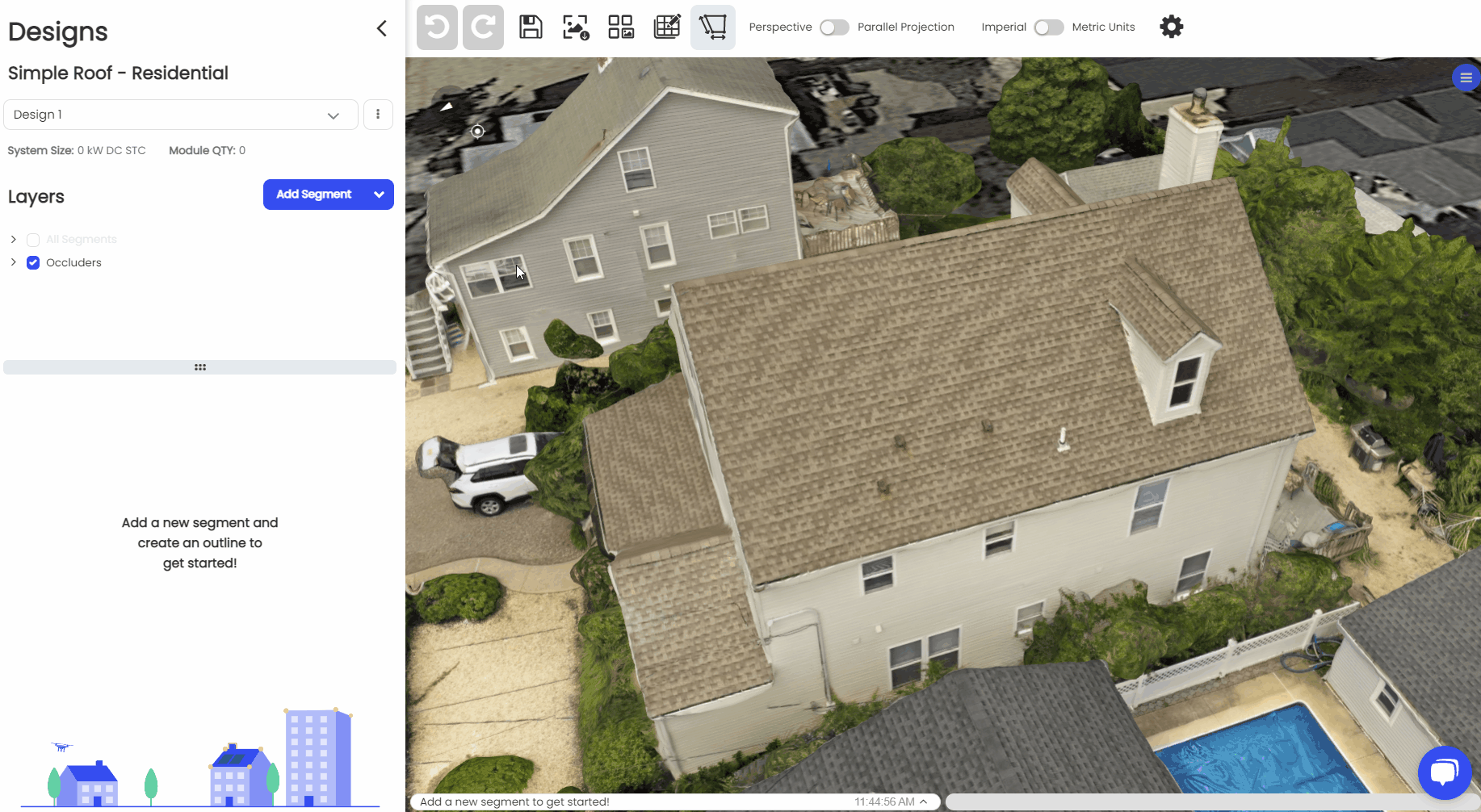
Creating an outline is your first step to designing a system in Scanifly.
Outlining Individual Roof Segments
The following steps can be taken in order to achieve the best results for outlining your roof segment.
- Orient to a view where you can see the whole segment clearly if possible.
-
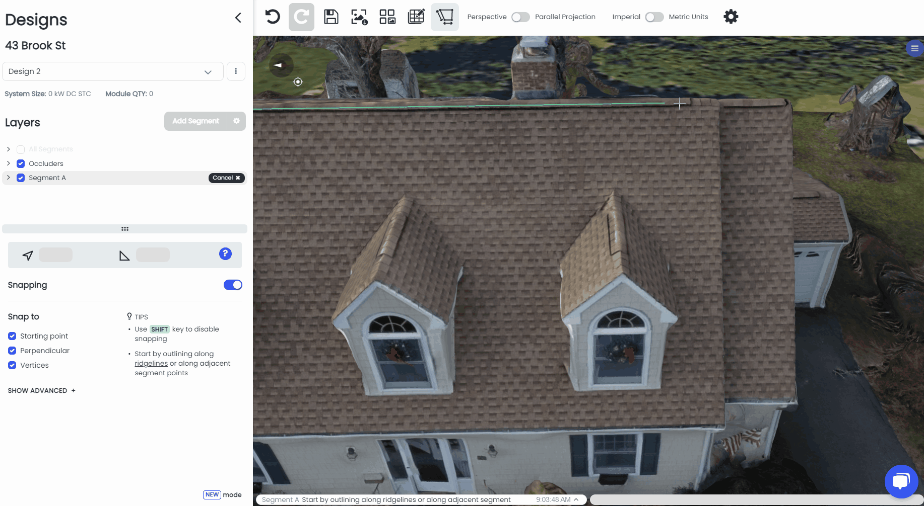
Click ‘Add New Segment’.
- Click on one end of the ridge and trace along the ridge first.
- After you place two points along the ridge, you will see a blue plane and a yellow square appear on the surface of the roof. Make sure the yellow square is showing on the roof surface you are currently outlining, not on another roof surface or off the roof entirely.
- When you see the blue triangle and the yellow square on the correct roof segment, hit ‘Enter’ and continue placing the rest of your segment points.
- After you set the third segment point, hitting "Enter" will automatically connect the latest point with the first one to close off the segment.
- When outlining adjacent roof planes, it's best practice to use existing points along a shared ridge or edge of a previously outlined roof segment.
Symbols
Parallel - This long equals sign will appear as you are drawing the side of a segment that is parallel to another side. In the GIF above, you will notice it as I am drawing the bottom line of the segment from right to left
Perpendicular - This sideways T will appear as you are drawing the side of a segment that is perpendicular to another side. In the GIF above, you will notice it as I am drawing the final side back to the starting point.
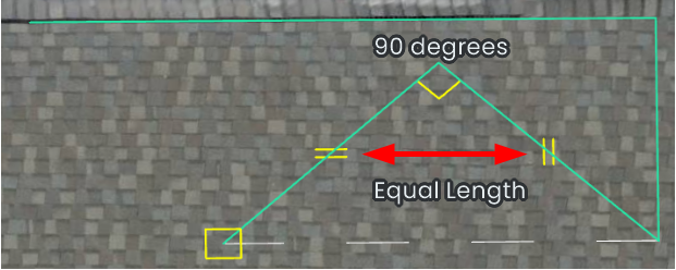
Equal Length - The symbol that appears when the segment line you are drawing is the same length as another line in your segment is two sets of small yellow lines that are perpendicular to each other. In the GIF above, you can see these symbols briefly right before I place my 4th and 5th points.
90 degrees - This symbol appears when moving a segment line and it becomes 90 degrees from the previous segment line. We also have a snapping feature which makes finding this angle easier.
Cursor - Once you have set your segment plane, your crosshair cursor will also have a yellow square around it, letting you know you are working in your defined plane.
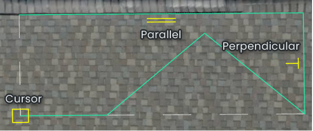
The Parallel and Perpendicular symbols will appear on the completed segment lines that are parallel and perpendicular to the line you are currently drawing.
The 90 degrees symbol appears between the last completed segment line and the one you are currently drawing.
The Equal Length symbols appear on the line you are currently drawing and any other completed segment lines that share it's current length.